Spencer Pollard
In Progress Data Acquisition GitHub
I began working in the lidar group in November of 2023 and worked over the winter break
separating the Fall 2023 and Spring 2024 semesters. My core project over the winter break is to
work on developing a new data acquisition program in Python moving away from LabVIEW for the REAL.
The new program should follow the flowchart below:
The data acquisition program should be sitting, waiting for a trigger event to begin data collection.
Once that signal is provided, the following things should all happen at the same time:
- Capture waveform data using the NI PCI-5122 Oscilloscope Card ✅
- Get azimuth and elevation angles from servo motor positions 🚧
- Get pulse energy ✅
- Get date and time ✅
- Get pitch and roll ❌
- Get Raman temperature and pressure ❌
(✅ means complete, ❌ means incomplete, 🚧 means partial completion)
My wholistic approach to this project will be to use Tkinter to create a GUI program to create the front end of the data acquisition software. I'm using Python because it's how I know how to do what is desired and because it's more "new user" friendly. If possible, I would like to translate the entire software to something like C which is faster than Python, but I don't believe speed is a current bottleneck.
Below represents the log where I will be recording my progress on the deliverables above to help guide future students who wish to resume my work.
Creating the GUI
My first approach to this was using Tkinter because at the time that's what I knew existed, and it wasn't until after I started when Dr. Eric Ayars informed me of the existence of PyQt5. I will show my initial DAC program followed by the most recent one. The DAC software should (for the most part) be a front end GUI application that simple shows the status of the data acquisition processes with a few controls to change whether or not the data is being broadcast on a network socket or whether or not the data should be written to disk.
Tkinter
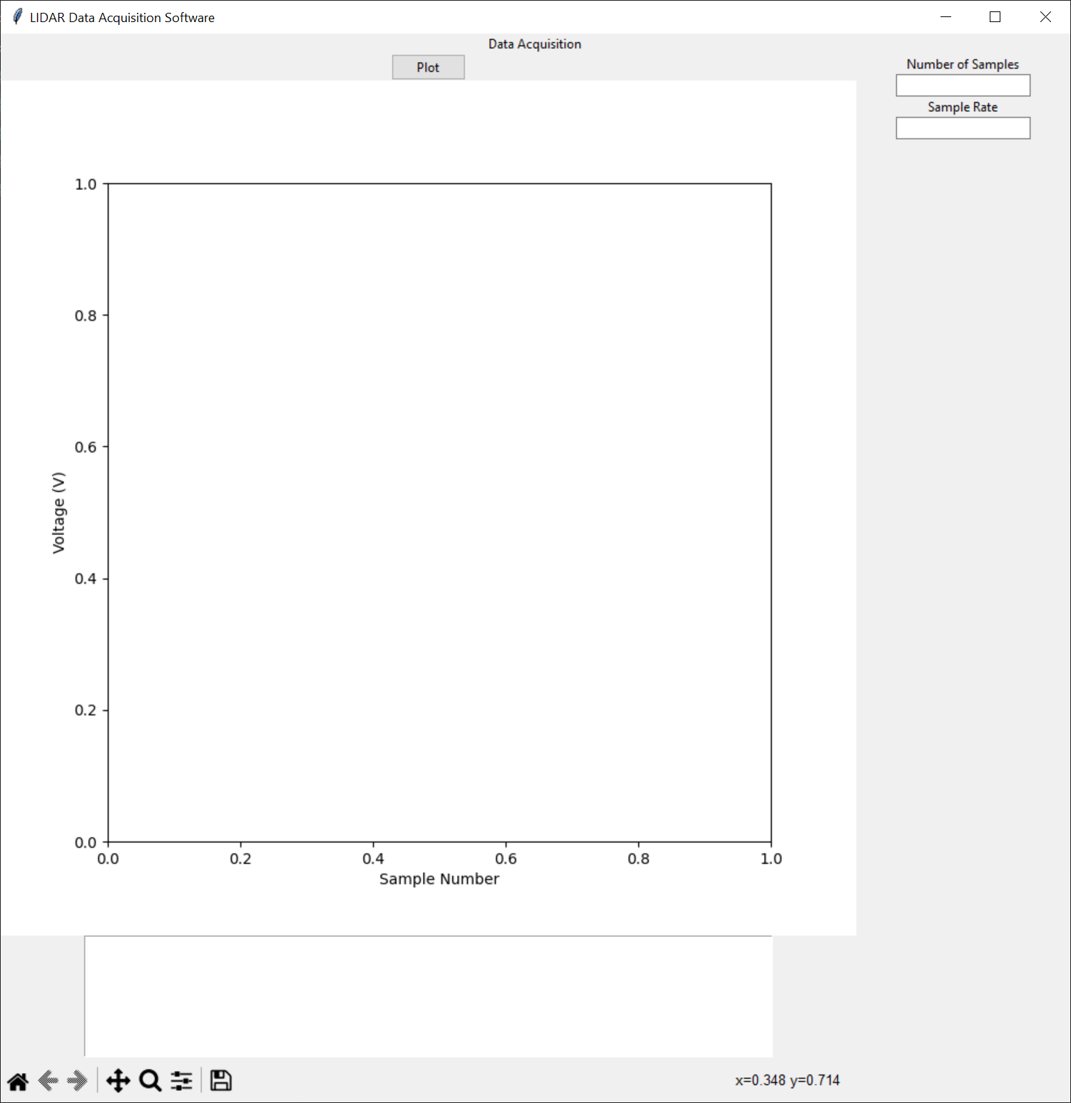
This first approach was attempting to combine and integrate all the different things that the DAC should be able to do and display them. I am not well-versed with Tkinter nor GUI design so my objective is just to get a window that works and will display everything that we need for data acquisition. What I will be doing is adding particular controls for the desired deliverables. For example, shown below is the state of the DAC application after integrating the waveform data collection.
PyQt5
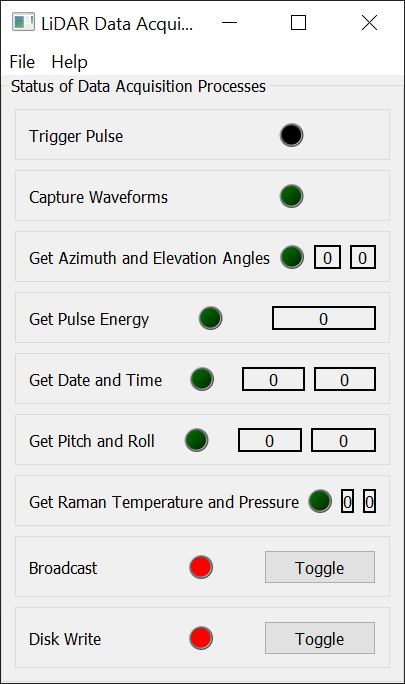
This second approach was centred around what the DAC should actually do. As mentioned above, the main DAC program runs while the LiDAR is operating and should simply display the statuses of the underlying data acquisition processes. Each box in the image below represents one of the core functions that this DAC program manages with a status light as well as a box that will display that reading. The topmost box with the trigger pulse is a testing light that will flash being triggered by the incoming signal to the PCI-5122 Oscilloscope card.
I wrote a "How To" here for how I went about interfacing NI DAQ peripherals where I show the exact code I used to interface the PCI-5122 card using Python. Basically, I'm taking the code from there and putting it inside a function that I can call from the main DAC program. That code is in capture_waveforms.py. The short answer for how I went about doing this is first look at how I can do this using NI MAX and begin translating that process to Python. Basically, for data acquisition you need a task (which NI MAX can do) and then you specify what that task should do (e.g. measure a voltage on a specific pin, count pulses, etc). In this case, we're measuring a voltage on an analog input pin. As of writing this, the current program for this requires a specific number of samples and a sample rate. I believe the correct approach to this would be waiting for data to exist before starting collection and then stopping once there's no more data. But for testing, this works just fine.
This was the longest and most complicated thing I have worked on relating to this project so far. The Animatics servo motors use their own proprietary language (similar to BASIC) to program them over RS-232 serial ports. So, I attempted to write a Python script that will allow me to build the instructions for the motor and send them. This script is the class that is in the animatics_motor_interface.py file. It creates a temporary directory and stores a log file there, and it creates a "program" object that has the ability to write to this logging file as well as keep track of the file's data (so it doesn't always reference a file for what data to write to the motor). This program object then has methods that allow the user to write specific commands to the motor (as also specified here). There are a ton of commands that these motors have so I'm more or less implementing the ones I need as I go. I don't know if the commands themself need to be in HEX, but I've encoded all the strings into ASCII before converting everything into HEX and then sending it over the serial line. This workaround makes it so the user doesn't have to deal with the SMI Interface to do anything with these motors, but the user will need to know how the program flow works [maybe make a How To for this?].
To do this, I am attempting to interface the Animatics Model SM3420D servo motors using an NI PCIe-6323 Multifunction I/O card with an NI SCC-68 Terminal Block. I built a couple of cables to properly connect the 7W2 Combo D-Sub Connector and P2 DB-15 D-Sub Connector with my computer and the PS42V6AG-110 48VDC power supply. I connected the positive and negative terminals of the CBLDC1 cable to the appropriate pins on the 7W2 Combo D-Sub connector and the remaining RS-232 data transmission related pins to a RS-232 connector. This allowed me to power the motor and communicate with it using the Animatics SmartMotor Interface (this was before I wrote my own Python interface). Once I could power and connect the motor, I needed to check the signal from the interal encoders to make sure the proper pulse trains are made and are measurable.
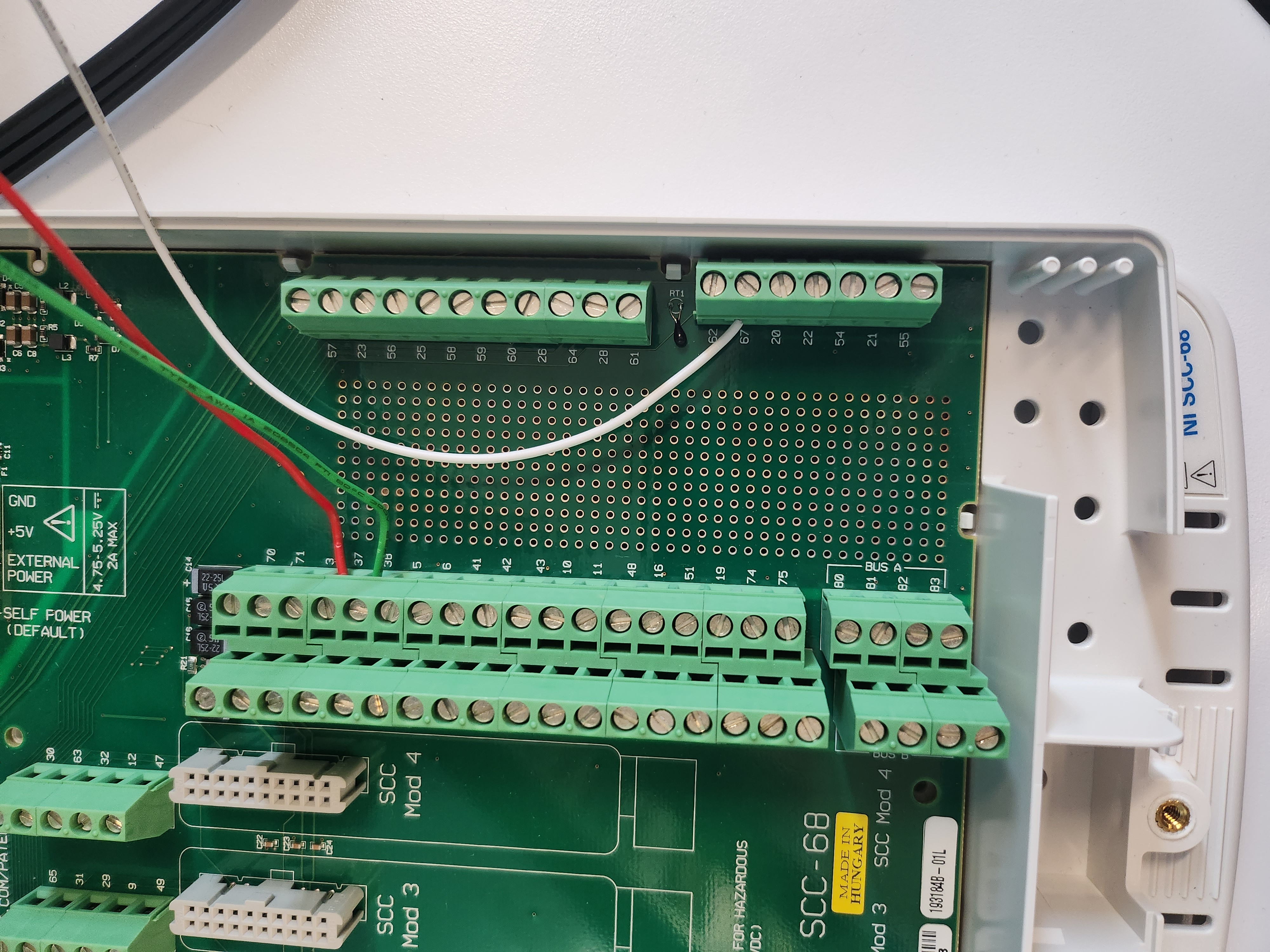
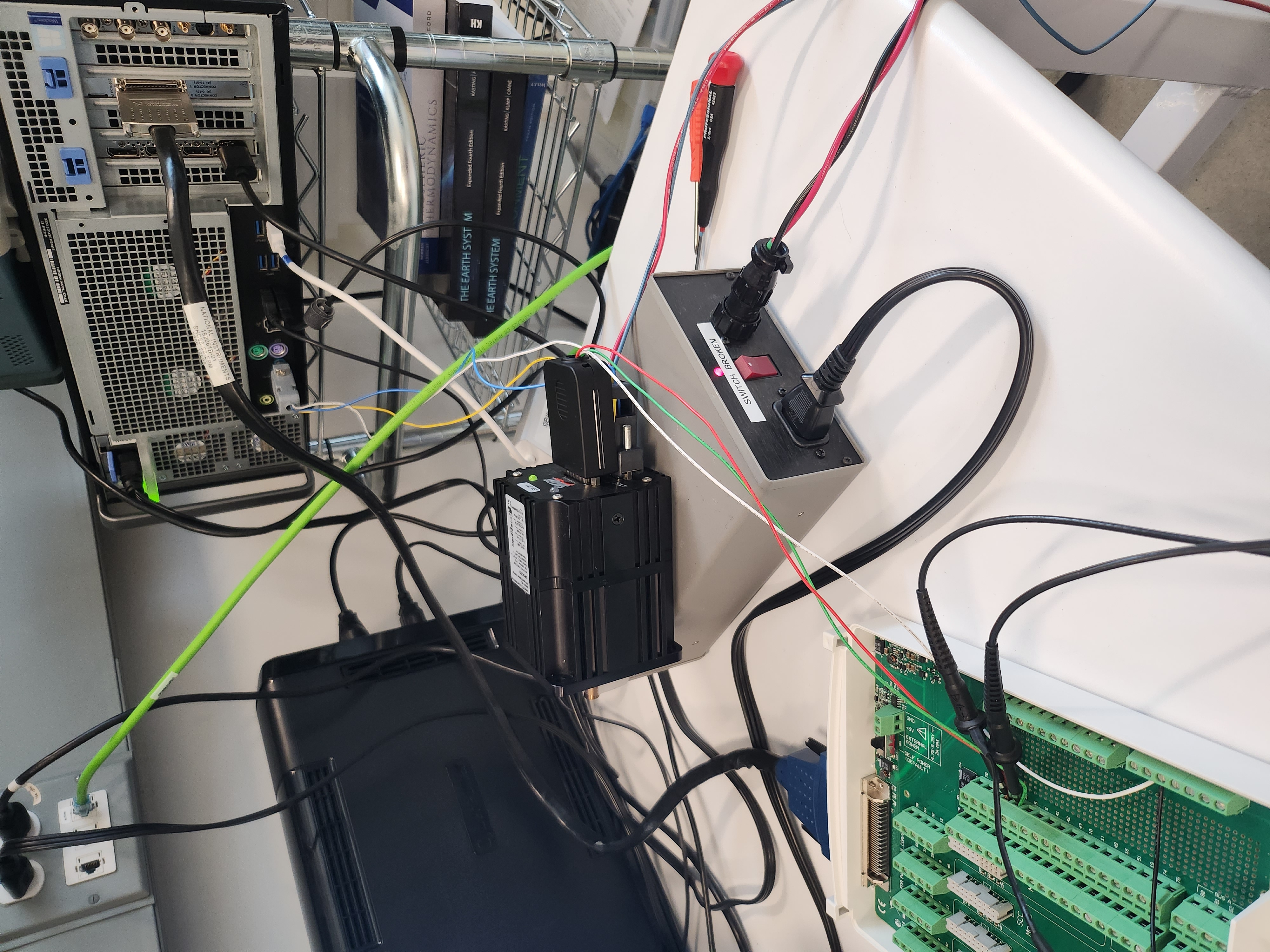
The leftmost image shows the screw terminals that I'm using from the SCC-68. The red wire is "Encoder A" from the motor screwed into terminal 37, the green wire is "Encoder B" from the motor screwed into terminal 45, and the white wire is ground screwed into terminal 67. These are based on the pinouts from the NI PCIe-6323 where pin/screw terminal 37 is CTR 0 A and pin/screw terminal 45 is CTR 0 B which are the default encoder channels for the counter in the NI task.
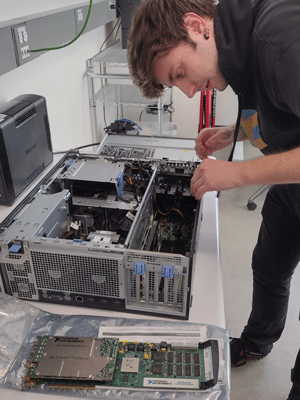
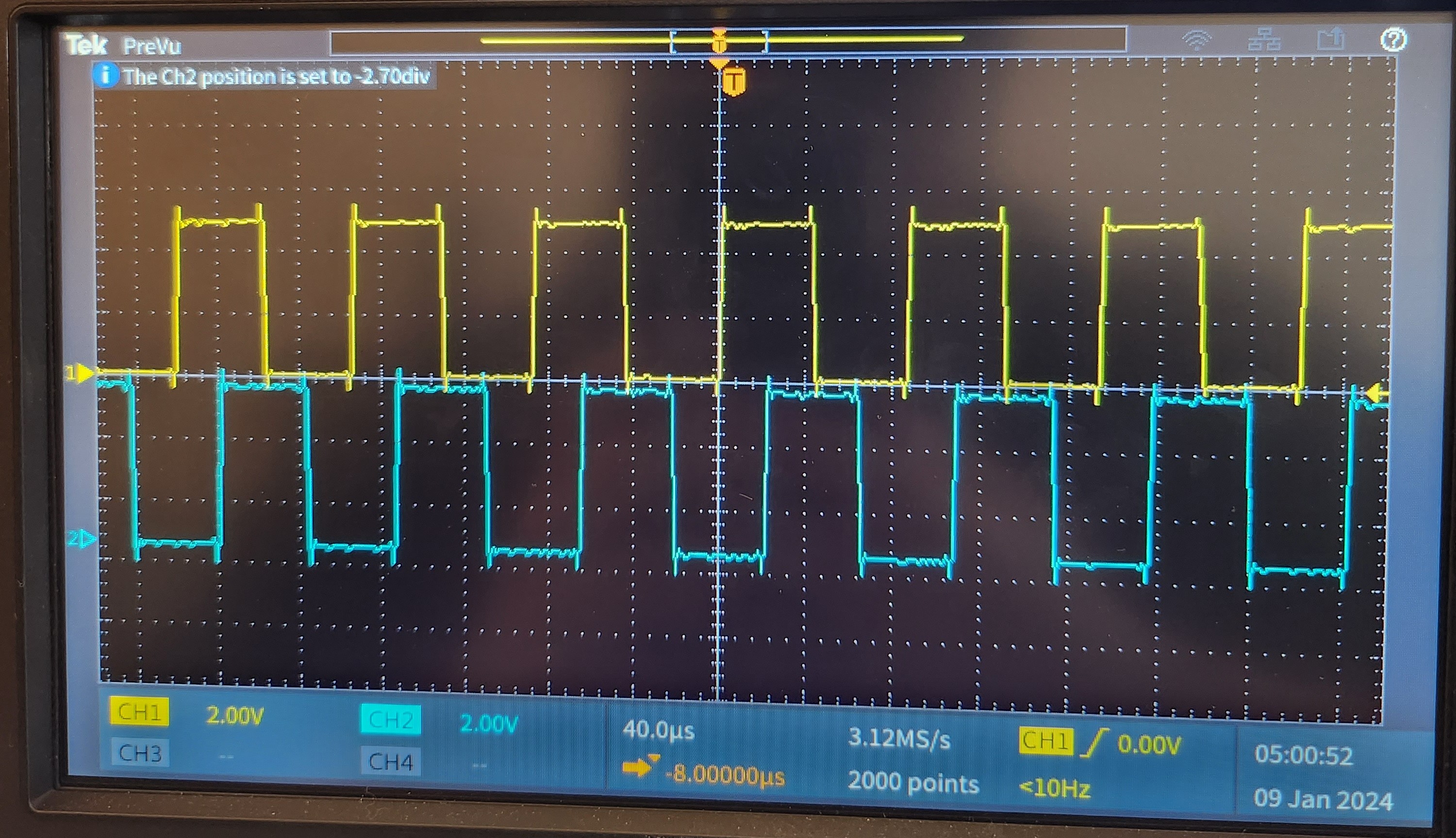
The centre image is just the rough setup I have showing that I have the motor plugged into both the SCC-68 and into the RS-232 port on my computer. The rightmost image is showing me the two different pulse trains from each encoder from the motor. These pulse trains should be 90 degrees out of phase.
From the pulse trains, we should be able to determine how far the motor moved from its initial zero point which means we should be able to determine the angle it's rotated at. With reference to motor_position.py, we can create a specific NI Task from NI-DAQmx designed for quadrature encoding using the
add_ci_ang_encoder_chan
to keep track of the motor's position. From there, we just need to manage the task using start and
stop methods and continually read from that channel to obtain the motor's position in degrees. However,
the pulses_per_revolution kwarg is 1000 which doesn't match any documentation for the motor,
but it results in values bounded between 0 and 360 degrees. At this point, the motors can be queried to
obtain the shaft position and it's now a math exercise to translate shaft position to azimuth or elevation
angles.
Getting the pulse energy was a bit easier than interfacing the motors. To get the pulse energy, we are using the Molectron EPM-2000 which fortunately uses SCPI for commands. All commands for the Molectron can be found at the provided link.
First, you have to enable the RS-232 port (or IEEE 488) using the instructions found here. To get started, we worked on writing a simple python interface to more easily send SCPI commands using the RS-232 port found in
laser_pulse_energy.py.
From here, we need to ensure that all of the serial settings between the two devices match. Based on
what is already being used in the REAL, we are using a baud rate of 38400, no parity, and 1 stop bit.
During testing, for reasons we're not sure of, when using a 4800 baud rate, the input buffer would
occassionally be padded by extra 'o' characters. But, when switching to a baud rate of 38400, the problem
went away.Note: When changing the baud rate of the Molectron, you need to power cycle the device for changes to take place.
When sending commands over serial, you need to have the correct line terminating character. In our case, the Molectron worked for a single carriage return (CR) character:
\r. For debugging
purposes, we found it helpful to enable the Moletron to echo back invalid commands using comm error on.
To constantly collect data, we set the output of the Molectron to 'continuous' using the command
out cont on. This makes it so that instead of the Molectron saving the readings to internal
memory, it constantly outputs the data onto the serial lines. To make sure the Molectron is properly set up to collect data on trigger pulses, you need to configure each channel to trigger using the external trigger. This is done using
ch a trig src extpos
to have channel 'a' trigger on rising edges. You'll also likely need to set the trigger level using
ch a trig lev 2 which sets channel a's trigger level to 2 volts.
This is very straightforward in implementation. I'm using the datetime libary's
now() function to get the current date and time of when things happen in the DAC software and just print them to a textbox for the time being. This is held in the DAC.py file (outdated) in the function get_date_and_time() where I'm formatting it in a particular way.
Getting pitch and roll along with Raman temperature and pressure are currently the most difficult because we don't have any spare parts for those sensors so we can't simulate the REAL inside the lab. Realistically, we think it might be easier if we're able to set up a testing data acquisition device inside the REAL and split off the current signals to the testing device so we can see if the new data acquisition software collects data the same way as the current system.
- Interpretting servo motor pulse trains to determine motor's relative position
- Get pitch and roll
- Get Raman temperature and pressure
Back to Lidar Team.